Below is a list of the available pre-defined
subcategories for each product type.
Below is a list of the available pre-defined
subcategories for each product type.The SKB offers pre-defined subcategories which trigger
specific logic to be used in the Selector. Many of the subcategories are
specific to the "Product Type" that the product line represents.
Pre-defined subcategories are accessed by clicking in the first cell of
any row under the Supplier ID column within the Product Line Options Subcategory
Table. (A drop down menu will appear). Although these are "pre-defined"
and trigger a specific set of logic, their descriptions are not, this
allows any naming convention to be used, however
always keep in mind the data they represent. A
pre-defined subcategory which is displayed in blue font, indicates
that it's options will expect an input value from the Selector user. To
see and example click here Below is a list of the available pre-defined
subcategories for each product type.
SC-HeadStr - This subcategory is used to
house the different head strategy options that the user can select. Five
head strategy options are available. See the SKB example below. To see
how it's presented in the Selector, click here. 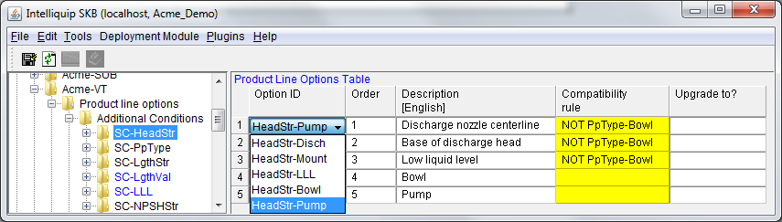
This SKB example shows different options for head strategy. These options
are offered in a drop down selection menu for which the user can define
during the selection process.
Options:
HeadStr-Disch - This will calculate the required head based on the user
specified head being measured at the discharge nozzle centerline.
HeadStr-Mount - This will calculate the required head based on the user
specified head being measured at the mounting surface. (Typical underside
of discharge head).
HeadStr-LLL - This will calculate the required head based on the user specified
head being measured at the user specified low liquid level.
HeadStr-Bowl - This assume that user specified head is measured at the
bowl.
HeadStr-Pump - This assumes that the user’s specified head represents the
pump performance based on HI. The use of this option will typically require
that the Selector’s pump performance calculation option to account for
static lift from LLL be unchecked and disabled. User privileges can be
setup to uncheck and disable the option by default.
SC-LgthStr 
This example shows 12 different options populated for length strategy.
Notice:
• Compatibility rules are
being used to control the applicability based on pump type.
• The options which are
sizing the column (and can) length using additional criteria are defined
by the checks in the Also size for LLL, Also size for NPSHa, and Also
size for Suction elevation cells.
SC-PressStr - This subcategory houses different pressure strategy
options for which the Selector user can define during the selection process.
See the SKB example below. To see how this is displayed in the Selector,
click here. 
This image shows the options available for pressure strategy. (PressStr-MaxRatedMCSF2EOC
& PressStr-MaxMaxSO2EOC are currently NOT supported).
Options:
PressStr-MaxRatedSO2EOC - This will calculate maximum working pressure
based on the maximum head generated at the rated impeller diameter. This
is the default condition.
PressStr-MaxRatedMCSF2EOC - Not supported.
PressStr-MaxMaxSO2EOC - Not supported.
PressStr-Rated-1 thru 4 - This will calculate maximum working pressure
based on the rated head for the rated impeller diameter multiplied by
the factor specified in the "Factor" column field. For example:
a factor value of 1.10 will calculate the maximum working pressure based
on the rated head at rated diameter plus 10%. Thus the description "Pressure
at rated conditions + 10.0%
SC-NPSHStr -
This subcategory houses the different NPSH strategy options for which
the Selector user can define during the selection process. See the SKB
example below. To see how this is presented in the Selector, click here.
SC-CanSuctionMinDist - This subcategory
houses the option(s) allowing the KE and/or user to drive the suction
elevation calculation. The calculation will be driven basis the reference
datum and the quantity of can diameters defined for the option(s).
The suction elevation will be calculated as follows:
1. If the subcategory exists:
• The minimum distance =
can diameter * specified quantity of can diameters as measured from the
specified datum (mounting surface or suction bell)
2. If the subcategory does not exist:
• For suction nozzles above
the mounting surface, the minimum distance from the suction bell to the
suction nozzle centerline will be 4 times the can diameter (inner).
• For suction nozzles below
the mounting surface, the minimum distance from the suction bell to the
suction nozzle centerline will be 2 times the can diameter (inner).
Shown below are some possible option examples:
Note: The low density option is shown to capture API market requirements.
The minimum 4D above the suction bell lip from the centerline of the suction
nozzle does not apply, as lower specific gravity liquids do not require
a run minimum length like water does.
SC-LgthVal - This subcategory houses
the different length value options which the Selector user can define
during the Selection process. The option presents the user a text box
in the Selector to allow input of the "length". What "length"
means is determined by the user's selection of "length strategy".
This information is used in the calculation of total pump length. For
example: If the Selector user defines the length strategy as "sump"
the sump length should default to 10 ft and also allow the user to change
the value to meet his particular conditions. In this case the Option ID
"LgthVal-1 was created with Compatibility rule "NOT LgthStr-Suct"
(remember the length strategy is sump) and it's default value is populated
with 10ft. Therefore any length strategy that the user selects, other
than LghStr-Suct, the "length" default
value is populated as 10 ft. See the SKB example below. To see how it's
presented in the Selector, click here . 
SC-VelCan - This subcategory houses
the options representing maximum can liquid velocities. The options present
the user a text box in the Selector to allow input of the maximum can
liquid velocity. For each option a default velocity is defined which will
be used if the user doesn't input a value. The Selector will use the velocity
value in sizing the can diameter. See the SKB example below. To see how
it's presented in the Selector, click here .
SC-WellDia - This subcategory houses
the options representing the maximum well diameter. The options present
the user a text box in the Selector to allow input of the maximum well
diameter to met their requirements. If necessary, a default well diameter
can be populated for the options, normally this will be set to 0. See
the SKB example below. To see how it's presented in the Selector, click
here .
SC-LLL - This subcategory houses
the options representing the low liquid level . The options present the
user a text box in the Selector to allow input of the low liquid level.
This value is used to determine the static lift required in applications
where the liquid level is below the mounting service. For each option
defined a default value is defined which will be used if the user doesn't
input a value. See the SKB example below. To see how it's presented in
the Selector, click here .
SC-FricCol - This subcategory houses
the options representing column friction rate limits. The options present
the user a text box in the Selector to allow input of the column friction
rate limit. For each option a default rate limit is defined which will
be used if the user doesn't input a value. The friction rate limit is
entered as a percentage based on ft/100. The Selector uses the value in
sizing the column diameter. See the SKB example below. To see how it's
presented in the Selector, click here .
SC-ElevSuct - This numeric subcategory
houses the option representing the suction nozzle location. The option
presents the user with an input box in the Selector to specify the distance
from the bottom of the mounting plate to the centerline of the suction
nozzle. (The value is positive when above ground and negative when below
ground.) This distance is added to the distance of (2xbarrel diameter
+ the distance of the end of barrel to the suction bell) . The total is
checked against the barrel length for which it can't exceed. A default
length can be defined which will be used if the Selector user doesn't
input a value. See the SKB example below. To see how it's presented in
the Selector, click here .
This SKB example shows the suction elevation option with a default of 12
inches (below mounting surface).
SC-ElevDisch 
This SKB example shows the discharge elevation option with a default of
12 inches (above the mounting surface).
SC-VelSuct - This presents the user a text box in the Selector
to allow input of the maximum suction nozzle liquid velocity. This is
used in sizing the suction nozzle diameter.
This subcategory houses the options representing maximum suction nozzle
liquid velocities. The option/options present the user a text box in the
Selector to allow input of the suction nozzle liquid velocity limit. For
each option a default velocity is defined which will be used if the user
doesn't input a value. The Selector will use the velocity value in sizing
the suction nozzle diameter. See the SKB example below. To see how it's
presented in the Selector,
This example shows the two can velocity options. The Vel-Suct-VCHead option
with a default value of 6.00 [ft/s] is used for a specific type of head
design. The Vel-Suct-Other option with a default value of 4.00 [ft/s]
is used for all other applications.
Note: The description field must be populate but are not used in the Selector.
The Selector displays "Suction nozzle liquid velocity limit"
regardless of the descriptions populated.
PD pumps are not currently supported in this version of the help file.
SC-SpeedinPick
SC-SpeedinSpec
SC-FlowMax
SC-FlowMin
SC-GearRatio
SC-GearTorqueLimit
SC-Gear
SC-DriveType